
Agree the surface, inspection stage and reporting basis before comparing quotations.
Before comparing machining quotations, mark the surfaces that need a controlled roughness, state their requirements and agree how the finished part will be checked. Purchasing can then compare what each price includes, while engineering can check whether the inspection evidence answers the drawing's requirements.
ISO 12179:2026, published on 8 May 2026, covers calibration and adjustment of contact stylus instruments. The required surface condition of a component still comes from its drawing and application. The checks below are purchasing recommendations, not additional requirements imposed by that standard. [1]
Mark the relevant faces, journals or bores on the drawing. Explain whether each surface supports a seal, slides against another part, forms a mating face or has an appearance requirement. Engineering should confirm which surfaces need individual limits and which can follow the drawing's general requirement.
Treat a roughness callout like a delivery address: a precise number is useful only when it points to the right place.
On a flanged end cover, for example, the mating face may need a different requirement from the outer rim. Showing that distinction helps the supplier price the work on each surface and tells the inspector where to measure.
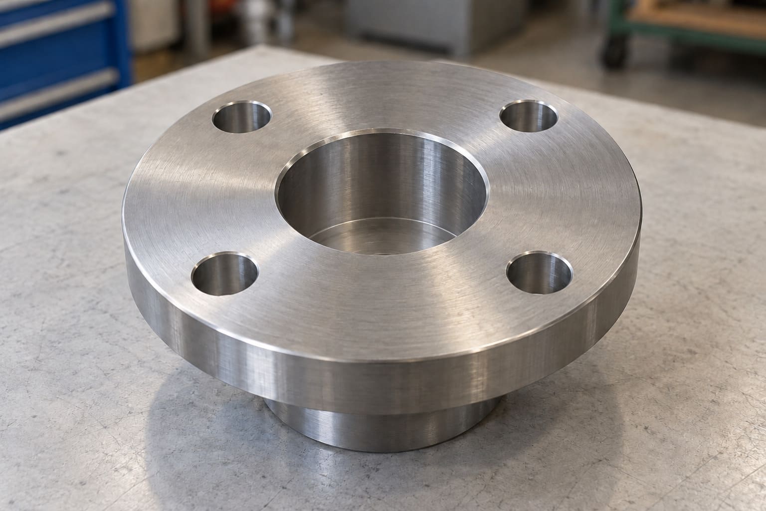
Identify the mating face that needs a controlled surface finish.
Include the parameter, limit, units and applicable standard edition. A number copied into an email without its drawing context can be misinterpreted, especially when customers and suppliers use different unit systems.
Ra is a commonly used average roughness parameter. It does not describe every peak, valley or local defect. Engineering should decide whether the surface's function calls for another parameter or a separate defect requirement. A roughness result alone cannot confirm flatness or freedom from scratches. [2][4]
When reusing an older drawing, confirm its intended measurement basis. Mahr's guidance on ISO 21920 describes changes to evaluation settings and support for previous standards in measuring software. Two reports showing Ra may still use different measurement settings. [3]
Ask the supplier to confirm that the proposed inspection method can reach the specified area. A short journal, narrow land or nearby shoulder may restrict probe access or the available measuring length. Resolve this during quotation; a convenient neighbouring surface is not automatically a valid substitute.
Agree the measuring direction and conditions with the quality or engineering team. Surface texture can be directional, so measuring in a different direction may change the result. Follow the drawing and applicable procedure. [2][4]
Specify whether acceptance applies after machining or after plating, polishing or another surface treatment. The report should identify the part's condition when measured. A reading from an earlier operation does not, by itself, establish the delivered surface condition.

Agree the inspection stage before production begins.
The report should identify the part and drawing revision, measured surface, parameter, units, applicable standard and inspection stage. Record the method and relevant evaluation settings, including the length of profile evaluated and any applicable filtering settings. [2][3]
Procurement does not need to choose every instrument setting. Engineering and the supplier can agree a controlled procedure, including any defaults allowed by the applicable standard, and reference it in the inspection plan.
Before placing the order, confirm how many parts will be checked and whether the quotation includes the required reporting. A certificate with a value but no surface identification or measurement basis gives the receiving team little help when checking the delivery.
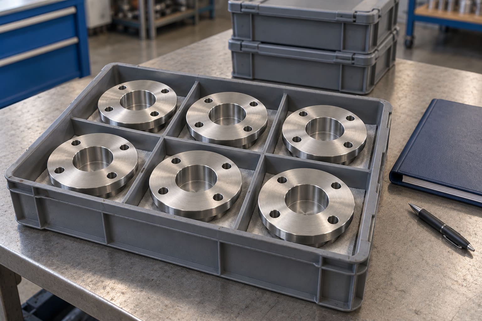
Agree the sampling scope and reporting requirements for the batch.
Agree who reviews a result close to the limit, what evidence they need and how a disagreement will be resolved.
If readings conflict, compare the measured location, direction, surface condition and evaluation settings before accepting or rejecting the parts. The quality team should assess measurement uncertainty and apply the agreed acceptance rule. Further measurements should follow an agreed procedure, with earlier results retained. [4]
Record any approved change to the inspection method, why it was made and how it affects acceptance.
KingTeam provides CNC turning, milling, Swiss machining, forging and stamping, and can coordinate surface finishing requirements. Send your drawing, material specification, surface finish, critical tolerances and expected volumes to kingteam@kingteam-cn.com, together with any surface roughness requirements. We can discuss the machining and inspection requirements before quotation.
Technical references
1. ISO, ISO 12179:2026: calibration of contact stylus instruments. Publication date 8 May 2026, verified in the official life-cycle record. Public scope consulted.
2. Mitutoyo, Surface Roughness Measurement, Bulletin 1984, December 2009. Used for basic measurement principles; its older acceptance rules and default-setting tables are not presented as current ISO 21920 requirements.
3. Mahr, Standard-compliant and future-proof measurement. Official explanation of ISO 21920 evaluation settings and support for previous standards. No publication date verified; accessed 20 October 2026.
4. National Physical Laboratory, Richard K Leach, The Measurement of Surface Texture using Stylus Instruments, Good Practice Guide No. 37, Issue 2, updated February 2014. Used for fundamental measurement principles and uncertainty considerations, not older acceptance rules or default settings.
All images are AI-generated illustrations. The workshop scene uses the supplied photographs as environment references. Images do not establish a measured roughness value or link the illustrated part to a particular machine.
 RETURN_LIST